Micropower |
Volume 2 · Number 3 · July 1982 |
| Page 20 of 37 |
|---|
is probably the easiest. Check that you still have +5V on your
Monitor and BASIC ROM and other RAM/
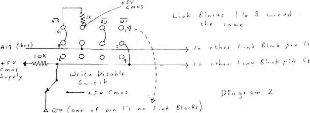
Next, obtain a 74LS156 and fit it an place of IC 44 (which is at present a 74LS155 of which the 74LS156 is an Open Collector version). This is necessary to allow correct power down operation. Fit 8 of 1K resistors between pin 3 and pin 4 of each Link block LKB1 – 8. This provides the Open Collector pull-up to the new battery backed, 5V supply, when it is fitted.
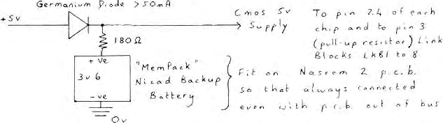
Now for the back-up supply. This is best done by reference
to diagram 2 where the normal 5V supply can be obtained from the
test pins near the bus connector and where the new 5V supply is
connected to the new RAMs and pull-up resistors ONLY. (It is
worth noting that another HM6116
could be fitted in place of the
Monitor and Video ROM/
Having now had this facility on my system for some while, I now wonder how I got by before it was fitted, and the time spent getting it right was well worth it.
| Page 20 of 37 |
|---|