Micropower |
Volume 1 · Number 1 · August 1981 |
| Page 25 of 33 |
|---|
Basic Form Of Mod
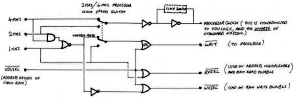
Nascom – 1 Implementation
| NOTE: | Gates Marked ‘OC’ are Open-Collector Outputs. WAIT Must be Driven by Such a Gate, to allow Common-Collectoring with Other Wait-State Generators |
| Page 25 of 33 |
|---|